Product Details
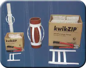
kwik-ZIP® 155 and 380 Series
Inert Centralizer Systems for the Drilling Industry
Including Installation Guide for 155 and 380 Series Casing Centralizer
 Revolutionary kwik-ZIP® Inert Centralizer and Spacer System
- Ideal for use with all types of casing, pipe, and screening, including PVC, steel, fiberglass, and gravel-packed screen installations.
- New GT Series – Ideal for small diameter drop pipe and Geo engineering applications, including rock bolts, soil nails, logging, sondes, etc.
- Rapid on-site assembly with lightweight, kwik-ZIP® segments.
- Fully adjustable Centralizer diameter — just add more segments!
- No pins, bolts, or welding.
- Easy and economical to transport in stackable flat segments.
- Corrosion resistant.
- Will not damage casing.
- Different Bow heights available for varied annulus sizes.
- Suitable for formation temperatures up to 176° F (HT Series).
- Satisfies Major Industry Standards such as:
- NGWA (USA) Manual of Water Well Construction Standards, 2nd Edition
- ANSI/AWWA a100-97: Water Wells
- ASTM D 5092: Ground Water Monitor Well Design
- Australian Minimum Bore Construction Requirements (including requirements for Inert Centralizers)

kwik-ZIP® 155 and 380 Series
The range of kwik-ZIP® 155 and 380 Series are available in 2 different bow heights:
- 155 HT-D 1.18″ Bow Height
- 155 HT-E 2″ Bow Height
- 380 HT-D 1.18″ Bow Height
- 380 HT-E 2″ Bow Height
The 155 Series will fit bar and pipe diameters ranging from 2.28″ OD to 7.09″ OD.
The 380 Series will fit pipe 6.3″ OD and greater. Both of these products are ideally suited for:
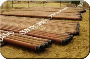
- Gravel-packed screens
- Casing
- Drop pipe
- Pump installation
| Model and Pre-Set Bow Height | Max Formation Temperature | Recommended for Use on Casing OD Nominal Diameter Range |
|---|---|---|
| 155 LT-D (1 3/16") | 104° F | 2" to 6" |
| 155 HT-D (1 3/16") | 176° F | 2" to 6" |
| 155 LT-E (2") | 104° F | 2" to 6" |
| 155 HT-E (2") | 176° F | 2" to 6" |
| - | - | - |
| 380 HT-D (1 3/16") | 176° F | 6" and above |
| 380 HT-E (2") | 176° F | 6" and above |
A special setting tool is required to install these products that are manufactured from a high-grade engineering plastic called Acetal POM.
2.28″ to 7.09″ diameter 155 HT Series (includes 155 HT-D, 155 HT-E)
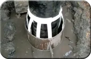
Applications: Grouted casing, gravel-packed screen, drop pipe, anchors, etc., with diameters greater than 2.28″
| OD of Bar, Pipe, or Screen, etc. | Units Required per Centralizer |
|---|---|
| 2.28" to 3.54" | 2 |
| 3.54" to 5.12" | 3 |
| 5.12" to 7.09" | 4 |
| Over 7.09" | Use 380 HT Series |
kwik-ZIP® Casing Centralizer Product Selection Criteria
A kwik-ZIP® centralizer model is available for all pipe, bar, or screen diameters above 0.70″ OD. A setting Tool is available for the 155 and 380 Series models to assist with correct installation. Select the appropriate kwik-ZIP® Casing Centralizer Segment Model for your application from the following table:
| Model and Bow Height (inches) | Service Temperature (degree F) | Recommended for Casing Diameter (nominal diameter range - inches) |
|---|---|---|
| 155 HT-D 1.18" | 176° F | 2.28" to 7.09" |
| 155 HT-E 2" | 176° F | 2.28" to 7.09" |
6.30″ and greater diameter
380 HT Series (includes 380 HT-D, 380 HT-E)
Applications: Grouted casing, gravel-packed screen, drop pipe, cased crossings, etc., with diameters greater than 6.30″
| OD of Bar, Pipe, or Screen, etc. | Units Required per Centralizer |
|---|---|
| 6.30" to 9.05" | 2 |
| 9.45" to 13.39" | 3 |
| 13.39" to 18.11" | 4 |
| 18.11" to 22.83" | 5 |
| 22.83" to 27.56" | 6 |
| 27.56" to 31.50" | 7 |
| Over 31.50" | Refer to Installation Guide |
kwik-ZIP® Casing Centralizer Product Selection Criteria
A kwik-ZIP® centralizer model is available for all pipe, bar, or screen diameters above 0.70″ OD. A setting Tool is available for the 155 and 380 Series models to assist with correct installation. Select the appropriate kwik-ZIP® Casing Centralizer Segment Model for your application from the table:
| Model and Bow Height (inches) | Service Temperature (degree F) | Recommended for Casing Diameterb(nominal diameter range - inches) |
|---|---|---|
| 380 HT-D 1.18" | 176° F | 6.30" and larger |
| 380 HT-E 2" | 176° F | 6.30" and larger |
Installation Instructions
Each 155 Series kwik-ZIP® centralizer segment has an effective maximum coverage of approximately 6.1″ (6.1″ circumference). Each 380 Series segment covers a maximum circumference of approximately 14.96″.
The tables below indicate the number of 155 Series and 380 Series kwik-ZIP® central segments required and the approximate setting position for various pipe diameters.
Size Table and Setting Guide
| Outside Diameter of Casing (inches) | Number of Segments | Approximate Setting Guide Position |
|---|---|---|
| 2.362 | 2 | 5 |
| 2.756 | 2 | 15 |
| 3.150 | 2 | 35 |
| 3.543 | 2 | 50 |
| 3.937 | 3 | 10 |
| 4.331 | 3 | 20 |
| 4.724 | 3 | 30 |
| 5.118 | 3 | 40 |
| 5.512 | 3 | 50 |
| 5.905 | 4 | 25 |
| 6.299 | 4 | 30 |
| 6.693 | 4 | 40 |
| 7.087 | 4 | 45 |
CAUTION: kwik-ZIP® centralizers should not be exposed to a naked flame or sparks from welding. Failure to shield the product whilst welding may result in ignition of the material or damage to the centralizer.
NOTE: Setting details shown are intended as a guide only. For casing and screen diameters not shown in the tables, use the formula outlined below to calculate the approximate setting position.
If the diameter of your casing is not listed on the above tables, the setting guide position listed for the diameter closest to that of your casing can be used as a guide. Alternatively, the following formula may be used to calculate the approximate setting guide position.
| Outside Diameter of Casing (inches) | Number of Segments | Approximate Setting Guide Position |
|---|---|---|
| 6.299 | 2 | 5 |
| 6.693 | 2 | 20 |
| 7.087 | 2 | 35 |
| 7.480 | 2 | 50 |
| 7.874 | 2 | 65 |
| 8.268 | 2 | 85 |
| 8.661 | 2 | 100 |
| 9.449 | 3 | 0 |
| 10.236 | 3 | 20 |
| 10.630 | 3 | 35 |
| 11.811 | 3 | 65 |
| 12.598 | 3 | 85 |
| 13.386 | 3 | 105 |
| 14.173 | 4 | 30 |
| 14.961 | 4 | 45 |
| 15.748 | 4 | 60 |
| 16.142 | 4 | 70 |
| 17.323 | 4 | 95 |
| 18.110 | 4 | 110 |
| 18.898 | 5 | 50 |
| 20.079 | 5 | 70 |
| 20.472 | 5 | 75 |
| 21.260 | 5 | 85 |
| 22.047 | 5 | 100 |
| 22.835 | 5 | 110 |
| 23.622 | 6 | 60 |
| 24.016 | 6 | 65 |
| 25.197 | 6 | 80 |
| 25.984 | 6 | 90 |
| 26.772 | 6 | 105 |
| 27.559 | 6 | 110 |
| 27.953 | 7 | 65 |
| 29.921 | 7 | 90 |
Where: D = Outside Diameter of Casing (inch)
Where: N = Number of kwik-ZIP® centralizer segments
155 Series: Suggested Setting Guide Position = [({D+4} x 22/7) ÷ N] – 98
380 Series: Suggested Setting Guide Position = [({D+6} x 22/7) ÷ N] – 258

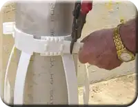 Step 1 – When you have established the appropriate setting guide position (see table), place the segments on a flat surface and insert the male section of each segment into the female coupling on the next segment, as indicated by the arrows in the above diagram (diagram shows 155 Series kwik-ZIP® Centralizer).
Step 2 – Line the leading edge of each female coupling up with the appropriate number on the Setting Guide.
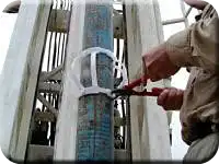
Step 3 – Once all settings are set, they can be wrapped around the casing and the final joints can be fastened. This method allows the centralizer to be made up mostly by hand. The setting tool should only be required to tighten the last joint once the segments are fixed to the casing. It is recommended that this final installation occur when the casing is hanging in the mast.
NOTE: The setting tool locks in behind the reinforced tabs at the rear of the female coupling. Open the jaws on the setting tool enough to reach the nearest tool lug and tension the centralizer collars enough to ensure that they will not move on the casing. Do not over tension the collars.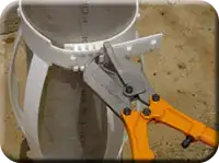 Step 4 – If necessary, adjust the bow height before fully tightening the last two couplings. This can be done by changing the distance between the top and bottom centralizer collars. (The bow height is preset to 1.18″; however, a rigid spacer under each bow ensures that the bows cannot collapse to less than 0.59″).
Step 5 – Once the centralizer has been tightened with the fastening tool, ensure that any excess length on the setting guide section of each segment is trimmed. This is easily done with a pair of tin snips or garden clippers and will ensure that the centralizer does not snag on formation when the casing is installed in the well.
NOTE: Snips are provided with the setting tool kit. The excess collar length should be trimmed as close as possible to the coupling.
Regulations regarding the use of centralizers vary between states; however, it is considered best practice to use one centralizer for each length of casing and screen. The Ground Water Well License / Bore License (if applicable) in many states also requires one centralizer for each length of casing.

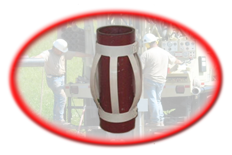
 Revolutionary kwik-ZIP® Inert Centralizer and Spacer System